
Part 1: Requirements management overview
Part 2: Defining requirements using ARIS business designer
Part 3: Design using ARIS UML designer
Defining requirements using ARIS business designer
Requirements traceability plays a key part when managing requirements during a project. In the illustration below you have a shortened version of a Meta model to manage requirements. In short, when using the concepts correctly it is possible to trace test cases to user stories to process objectives to project objectives.
.png)
When using ARIS the above concepts can be visualized using ARIS objects as illustrated below.
.png)
Let’s take a practical example, i.e. Books R Us wishes to extend their services with an online ordering capability. In the Concept Phase we will use a Project Context diagram to identify the project objectives, impacted stakeholders and in scope processes. See example below for Books R Us Online Capability – Project Context diagram.
.png)
From the project context diagram one then defines the business objectives per in scope process using a function allocation diagram. Let’s have a look at the business objectives for Create B2B Order:
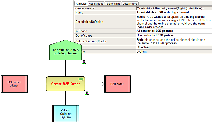
From the process context diagram (Create B2B Order) one can then define the end to end process. In my example BPMN was used to define the process. From this one can “tag” the tasks to indicate if there are any changes required or if the task is already in production by using the relevant status i.e. New, Mod or Prod? For each task where you have a status of either New or Mod you will then identify requirements as user stories.
.png)
From the above it is clear that Validate batch, Extract Transactions & Place Order are all new functionality. I will now define requirements for Place Order by associating user stories (Requirements object) to the task using a Function Allocation Diagram:
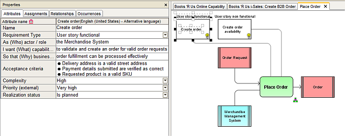
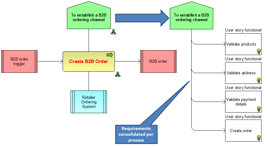
A Requirements Tree is then assigned to the objective of the parent process to consolidate all the identified requirements (user stories) for the in scope process. The above process is repeated for all in scope processes.
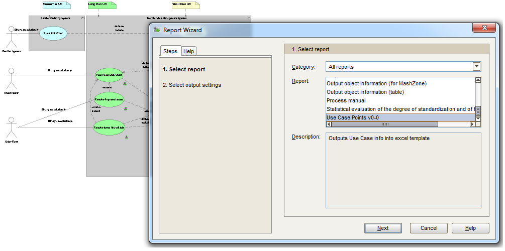
A consolidate use case model can then be created to indicate the in scope system functionality which relates directly to the defined processes. The use case model identifies the key actors (human & technical) and is then used to estimate the duration and effort of the overall project using use case point calculations. This is done in the Scope Phase also known as the “mile wide, inch deep” view of the project.
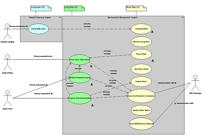
A custom script was developed to calculate the effort using use case point calculations based on the work of Gustav Karner of Objectory AB (later acquired by Rational Software) developed the use case points method of software estimation (Karner 1993).
It is also possible to use a Structuring model to structure the content (much like a table of contents) for the deliverable that you want to generate directly from the repository. In the example above one would structure the content and then generate an HBRS (high level business requirement specification) directly from the ARIS repository using a custom script called EasyReport.
.png)
To summarize, this section covered the key concepts conducted during the scope phase to produce a high level business requirement specification (HBRS) that defines the product scope based on the identified sea level use cases. The product scope can then be estimated using use case point calculations based on the identified sea level use cases. Another key deliverable in the scope phase would be an initial solution architecture design (SAD) for projects where you are introducing new technology or extending current solution architectures – this was not covered in the article.

In Part 3: I will explain how ARIS UML designer is used to designs the software requirements
Yubhesh Chaudhari on
Very helpful. Thanks Etienne for sharing this.
Which ARIS model type you have used to create Project Context diagram. In ARIS IT architect this model type is not present. I can create this with VACD model also. But want to understand which model you have used for Project Context diagram & which ARIS tool (ABA,ITA...)?
//Yubhesh