
This recipe works very well for those who want to fit making homemade bread into their weekday work schedule. Although the final product takes quite a long time to produce, this is mostly hands-off waiting time.
All ARIS Express models

Currently, my colleagues are publishing articles about many new or improved ARIS features. In their articles, the authors often use some terms common to everyone working in the development department of IDS Scheer. My feeling is that it is sometimes a little bit hard to follow those articles if you are not aware of those terms. Therefore, I want to introduce the most important terms today in a nomenclature (or taxonomy).
Attached to this post, you will find a nomenclature as ARIS Express model. I highlighted those terms, which are most crucial to know. Also, the nomenclature is not complete, because I left out some terms, which are not often used in public anyway like the "Change management" dialog of ARIS designer.
On a first glance, we are talking about server and client. The ARIS Business Server is the part of ARIS where all your models are stored and managed. This server is usually handled by your ARIS administrator and you are not confronted with it. Therefore, I have not included the server in my nomenclature. Instead, I focus on the part you work with: ARIS client.
The ARIS client comes in different flavours such as ARIS Business Architect, ARIS Business Designer, ARIS IT Architect, ARIS SOA Architect, ARIS Business Rules Designer, etc. All those different instances of the ARIS client share a common user interface. Therefore, my nomenclature just talks about the ARIS client, but not about the different flavours.
I divide the client in menu, toolbar, and modules.
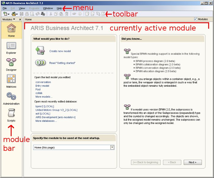
Menu (sometimes also main menu or menubar) and toolbar are probably familiar to you, because you will find those elements also in other software packages. The more interesting part is below toolbar and menu. This area shows the module bar and the currently active module. Depending on the flavour of your ARIS client, the module bar will show different icons. After selecting a module, the module is shown in the big area next to the module bar.
There are different modules, but the most important modules are:
- Explorer
- Designer
- Administration module
- Script module
The administration module is only available if you are using an ARIS XYZ Architect flavour of the ARIS client. This module is used to administer ARIS databases, users, filters, etc. In the script module, you can define and execute reports and macros. You can either program them in the script editor or use the WYSIWYG editor.
Most of the daily modelling and process analysis work is done in the modules Explorer and Designer. Let’s first take a look at explorer.

Explorer is divided into 2 main parts:
- The tree on the left shows all ARIS databases available on the server (in case you are using an Architect flavour of the client) and the content of the currently database or group.
- The list on the right shows the content of the currently selected object in the tree. For example, if you select a model in the tree, you will see a list of all contained object occurrences.
Explorer is used to navigate to models, manage the group structure of a database, to open a database, etc.
Modelling is done in designer. Designer is probably the most important module where you do most of your work with ARIS. Here is a screenshot. Please note I had to resize the window heavily so that all important components are shown. This leads to some artefacts like the missing colour of the menu.
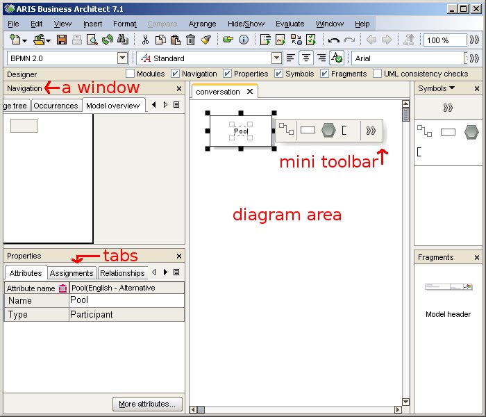
It can be seen there are many different areas in designer. The biggest area is showing the current diagram. You can use the tabs on top of the diagram area to switch between different diagrams. Diagrams are also called models in ARIS Method. A model consists of objects and connections. An object can occur several times in a diagram or even in multiple diagrams. We call these occurrences. If you click on an object, a small toolbar will appear next to the object. This toolbar is called mini toolbar.
Besides the diagram area, different windows can be shown in designer. The most important window is probably symbol bar. You use it to add new objects to your model. Fragments is another window. Here, you access often used modelling constructs.
Other designer windows such as Properties and Navigation consist of several tabs. Tabs divide windows into different views. In the navigation window, you got a tab showing the explorer tree again as in the explorer module. To not mix up both, it is often called explorer tab or designer’s explorer.
If you right-click on a model, object or connection, a context-menu is shown. The context menu provides access to many additional actions, which you apply to the selected object. You can also access those actions in the menu. For example, you can open the attribute dialog or the property dialog for the selected object.
There are many more terms used while talking about ARIS. But I hope this gives you a good overview. You might be also interested in this article, which describes what ARIS and related terms like ARIS Value Engineering or ARIS Method mean.


Overview
With the shipment of ARIS SR 2010_05 also the integration with webMethods 8.0 (SP1 with Fix pack 2) was officially released.
There were already some questions in the community about the scope of the integration or the next steps. In this article I want to give you some insights and show how the integration approach works in detail.
The first integrated use case we support is “Process automation”. That means customers can use their business processes as direct input for the IT department so that the IT guys can implement these processes.
The business analyst can define business processes in form of EPC process models. He can browse the repository for appropriate business services supporting the process or organizational elements (roles, person types, organization units, etc) carrying out certain process steps. Further it is possible to define KPIs (which were set up in the strategy phase of the project) to measure functions in the process.

After the business analyst finished his work, the process can be transformed to a logical process (this process is more concrete, but does not deal with any technical stuff). This step is fully automated by a transformation from EPC to BPMN 2, which is based on the ARIS transformation framework. As the details about this transformation would go beyond the scope of this article, I would like to dicsuss this topic in another post. The transformation considers the complete control flow, services, KPIs and organizational elements, which were defined in the business process.
Afterwards the BPMN 2 process can be reworked by a role we call process engineer. His job is to add information about software services which are realizations of the business services used in the business process. Additionally he can define further steps which are not business relevant, but are a meaningful input for the later implementation.
The BPMN 2 process can now be exported to webMethods BPMS. Currently the data exchange between ARIS and webMethods BPMS is based on XPDL 2 due to the fact that the BPMN 2 serialization format is still under development.
Example
So let’s have a look at a small example which is also available as a step by step example shipped with ARIS (see ARIS help „Work with objects and models/Create service-oriented models/Example – SOA implementation with ARIS SOA Architect and webMethods designer”).
The business analyst starts and designs a process for booking an invoice.
In order to book the invoice it is necessary that the debitor already exists. In case the debitor does not exist a new one should be created. In order to keep track of the number of newly created debitors the analyst defines a KPI and associates it with the process step. In case the invoice amount is greater than 100 000 € the financial accounting must approve the invoice. Last the invoice is booked. This step is supported by the business service “Invoice management”.
.jpg)
The business analyst transforms the process to BPMN so that the process engineer can perform the steps necessary to share the blueprint with the IT.
As you can see the transformation automatically creates lanes based on the services and organizations participating in the process. Further we can easily distinguish between service tasks and user tasks by just having a look at the symbols being used.
.jpg)
The KPIs are also attached to the steps in BPMN in an allocation diagram as BPMN 2 does not cover any constructs for defining KPI information.
The diagram can now be exported to an XPDL file which contains infomation about
- The process flow also including visual information like diagram coordinates or colors
- Web services used in the process
- KPIs used in the process
- Organizational elements used in the process
The developer can import the XPDL file into webMethods Designer. The import automically detects referenced services and imports them into thewebMethods Integration Platform. Also participants that are carrying out process steps are imported into the designer as well as the information about KPIs as shown in the screenshot below.
.jpg)
I know that the future roadmap is also a hot topic for a lot of people visiting ARIS Community. As soon as we have defined it completely, we will give you an overview of what is coming with the next releases.


In my last post, I showed you how process modelling works by visualizing cooking recipes.
Of course, I haven´t modelled straight on, but I had to follow some "basic rules of EPC modelling".
Therefore, I show you today which basic rules exist.
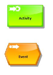
An Activity (or Function) describes an incidental task that typically consumes time and resources. Therefore, it is an active component and has decision-making authority.
An Event describes, in accordance with DIN 69900, an occurred defined condition that causes a sequence of activities. Therefore the event is a passive component and may have no function in contrast to the decision-making authority. Events can trigger functions. Functions are triggered by events. Events describe an occurring condition.
Short overview of Rules
Generally, you start with an Event, if you model an EPC.
A number of Activities can follow an Event. In the past, it was said, that Events and Activities must alternate. This leads to very long process models with a lot of trivia events. Therefore, we suggest today to only add an event, if an important state change needs to be documented.
Recommendation, when using Events:
- at the beginning of the process or after start-process interfaces
- at the end of the process or before the end of process interfaces
- Decision events by XOR or OR connectors
- for important events, for example Milestones in project
Activities or Events must not have more than one outgoing or incoming Connection.
.jpg)
The control flow of the process is modelled using Rules (gateways).See afterwards, which Rules exist.
Rules can be used as follows:
- Of exactly one ingoing Connection follow a number of outgoing Connections (SPLIT).
- Of a number of ingoing Connections follow exactly one outgoing Connection (JOIN)
A sequence of Rules is possible.
An EPC is generally closed with the same operator like it was opened.
You end the EPC with an Event.
Logical operators
In an EPC you can use following Rules:
.jpg)
SPLIT: The processing steps that follow the rule occur in parallel and have to be performed.
JOIN: All processing steps for incoming connections must be completed so that the processing steps that follow the rule can be performed.
SPLIT: Exactly one of the following rule processing steps must be executed.
JOIN: Only one of the processing steps for incoming connections may be completed so that the processing steps that follow the rule can be performed.
SPLIT: At least one of the following rule processing steps (or even several or all processing steps) must be performed.
JOIN: At least one processing step (or even several or all processing steps) must be completed, whereupon the processing steps that follow the rule can be performed.
For logic operations between Events and Activities, there are special rules, which are shown in the ARIS Express model attached to this post. For your convenience, I also added a screenshot of the rules below:

I put this summary of the rules next to my monitor while modelling. It helps me a lot. I hope it helps you, too! So long, have fun modelling till my next post.
We just created a new BPMN Community group to discuss BPMN modeling, BPMN specification, BPMN best practices, etc. Feel free to join!
To kick off the discussion, I like to collect some BPMN best practices. BPMN was designed by a big vendor committee and not by users. This usually leads to a very complex specification containing a lot of things nobody needs. Don't get me wrong here: I don't blame the people involved in specification process, it is just how things are.
Attached is an ARIS Express BPMN 2 model, which I want to extend with your BPMN best practices. Initially, I added one of the biggest problems I have with the specification: I can't remember what an empty gateway means! Every time I see a diagram using empty gateways I have to look up if such a gateway is an exclusive or an inclusive one. So far I haven't found any memory aid.
Actually, I'm not looking for a memory aid at all, because I think it is a big fault in the specification that it got symbols not clearly telling their meaning. Symbols and icons with unclear meaning are not accepted in visual design, so why do we accept it in a public modeling standard? The solution is simple: Don't use an empty gateway icon, but instead use the exclusive icon with the "X" in it. I think everyone can easily remember that the "X" stands for eXclusive and that the plus sign of an inclusive gateway stands for the AND operator.
So what are your BPMN best practices? Please post below and I will add them to the file above so that in the end we get some kind of cheat slip for good BPMN modeling.
In my last post, I showed to you a simple process modeling example based on the “Schwenker” menu from Saarland. The process used was just a step-by-step instruction. Today, I show you a little bit more complicated process in order to prepare “Mehlknepp”.
Have you ever been in Saarland for a culinary journey? Saarland has four „Michelin-Star houses”. Two of them are the Victor`s gourmet restaurant Schlossberg in Perl- Nennig of Christian Bau and the guest house in Saarbrücken of Klaus Erfort. They achieved the best evaluation with 3 stars. Those restaurants belong to the nine best restaurants of Germany.
Everyone could cook in a saarländisch way, let´s see how:
Compared to my previous process model, this one is a little bit more complex. It includes a loop to ensure the Mehlknepp have the correct consistency before they get boiled. If they don’t have the correct consistency yet, you need to add milk or flour.
There are different possibilities to experience the “Mehlknepp”. You can take them as starter with salad or as main dish for example as “Geheirade” (another Saarland menu but you have to mix them with fried potatoes) or as dessert with apple sauce.
Serve them with sauce or escallop them! “Mehlknepp” are easy to cook and easy to variegate!
So long, have fun cooking “Mehlknepp”.

I have lost a bet last week and had to cook "something special" for my girlfriend for five days :-). Turned out cooking is fun and can easily become a passion (just like BPM). Here is one easy and wonderfully tasting recipe I have fixed during my bet redemption. Try and you won't regret :-).